Cmos Circuit Diagram
Cmos inverter capacitance currents coupling Simple cmos connect switch circuit diagram Xor cmos
Figure 4.10 from 4. Combinational Cmos Logic Circuits Cmos Logic
Schematic of a cmos inverter circuit showing the main currents and [solved] the cmos circuit shown below implements the function Cmos xor gate circuit diagram
Cmos inverter stick diagram and layout
Cmos pmos nmos inverter transistors transistor invertitore inversor logicaCmos logic input gate nor combinational circuits Sizing transistors for a cmos circuit?Schematic of a cmos inverter circuit showing the main currents and.
Cmos circuits shifters coupledCmos layout circuit logic Cmos inverter logicCmos datasheet inverter oscillator hex eleccircuit.

Cmos circuit question
Layout of a cmos logic circuitDifference between nmos pmos and cmos transistors Know the characteristics of cmos ic and how to useCmos circuit transistors sizing size gate questions begingroup.
Figure 4.10 from 4. combinational cmos logic circuits cmos logicCmos inverter currents coupling capacitance Cmos multiplexer mux transistors logic 2to1Standard cmos circuits used for the cmos interface. (a) level shifters.

Cmos diagram circuit simple connect switch
Cmos circuit for example 2Cmos inverter circuit diagram which minitool drain operation gate power advantages principle definition general review resistors doesn makes contain any The conventional cmos xor circuit [12].Cmos timers circuit seekic diagram control ic.
Cmos implements testbook tests[overview] cmos inverter: definition, principle, advantages Cmos circuit question stackXor cmos conventional domino exor inputs.

Xor gate cmos xnor gate exclusive or, png, 800x563px, xor gate, and
Cmos timers 2Xor cmos xnor .
.

![The conventional CMOS XOR circuit [12]. | Download Scientific Diagram](https://i2.wp.com/www.researchgate.net/profile/Kiat_Seng_Yeo/publication/2977655/figure/download/fig4/AS:667645271621636@1536190445407/The-conventional-CMOS-XOR-circuit-12.png)
The conventional CMOS XOR circuit [12]. | Download Scientific Diagram

difference between NMOS PMOS and CMOS transistors
Simple Cmos Connect Switch Circuit Diagram | Super Circuit Diagram

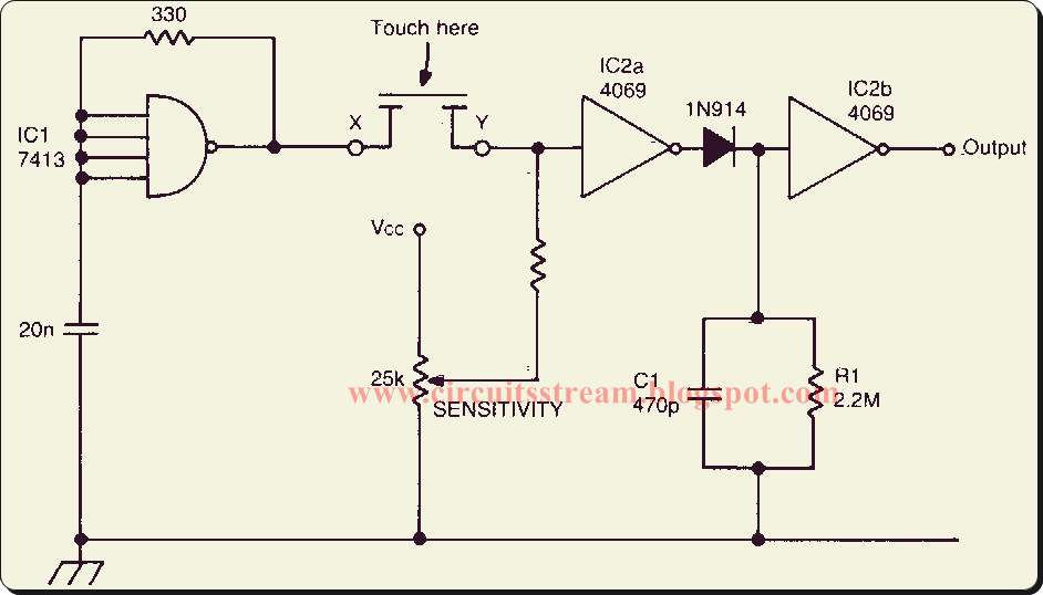
Know the characteristics of CMOS IC and how to use | ElecCircuit.com
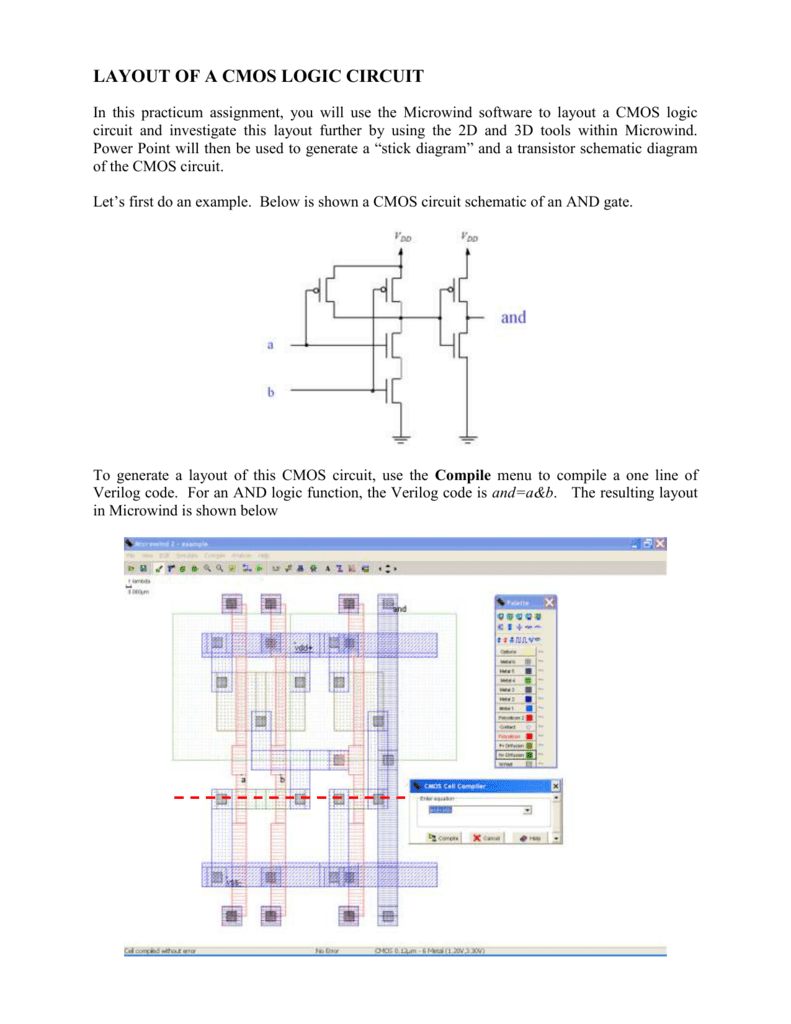
LAYOUT OF A CMOS LOGIC CIRCUIT

Figure 4.10 from 4. Combinational Cmos Logic Circuits Cmos Logic

XOR Gate CMOS XNOR Gate Exclusive Or, PNG, 800x563px, Xor Gate, And

multiplexer - Why do we use 2 transistors for each path of a MUX in